How to use MCP23017 I2C IO expanders with the Raspberry PI and Circuit Python? What about connecting a Rotary encoder to your Raspberry PI?
Like me, you may have a small project to connect one or more rotary encoders to your Raspberry PI. The MCP23017 chip seems ideal for this, and is easy to connect to the Raspberry with its I2C bus. Let's see how to use it with Circuit Python for Raspberry.
Connecting the MCP23017 to the Raspberry
Here are the connections I've chosen, MCP to Raspberry PI 3 bus
- pin 12 SCK => pin 5
- pin 13 SDA => pin 3
- pin 20 INTA => pin 36
- pin 19 INTB => pin 37
Note that I have supplied the MCP23017 with 5 volts. This won't cause any problems with the Raspberry, which communicates in 3.3 volts, as the I2C bus is driven by a low state on the MCP side, so the Raspberry will never see 5 volts on its IOs.
using the I/O expander with Circuit Python
First of all, make sure you've enabled the I2C bus on the Raspberry!
$ raspi-config
  => Interface options
   => I2C enable
Then, if you haven't already installed Circuit Python for your Raspberry, Adafruit Blinka, follow the setting up the 'venv' here.
In your Venv Circuit Python, install the MCP230xx library:
pip3 install adafruit-circuitpython-mcp230xx
We can now start our Python script with these lines to load CircuitPython on the Raspberry and initialize the MCP23017. Mine responds to I2C address 0x21, modify if necessary:
import board
import busio
import digitalio
from digitalio import Direction
from adafruit_mcp230xx.mcp23017 import MCP23017
import time

i2c = busio.I2C(board.SCL, board.SDA)
mcp = MCP23017(i2c, address=0x21)
The following code will enable us to check that everything is communicating correctly with our Raspberry. Pin 0 of the MCP will be used as Input and Pins 1 and 2 as Output, whose state will alternate every half-second:
pin0 = mcp.get_pin(0)
pin1 = mcp.get_pin(1)
pin2 = mcp.get_pin(2)

# set pin 0 as input with a pull-up
pin0.direction = Direction.INPUT
pin0.pull = digitalio.Pull.UP

# set pin 1 and 2 as outputs
pin1.direction = Direction.OUTPUT
pin2.direction = Direction.OUTPUT

while True:
  # check pin0 value
  print(pin0.value)
  pin1.value = True
  pin2.value = False
  time.sleep(0.5)
  pin1.value = False
  pin2.value = True
  time.sleep(0.5)
What's great about Circuit Python is that this code will work just as well on our Raspberry Pi as it will on a much simpler microcontroller.
Furthermore, this versatility ensures seamless integration across a wide range of hardware platforms, from high-performance devices like the Raspberry Pi to more modest microcontrollers, making it an incredibly accessible and adaptable tool for all levels of electronic projects.
Rotary encoder with MCP23017 and Circuit Python
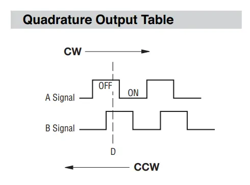
A rotary encoder utilizes two-phase signals to track rotational movement. As the encoder shaft turns, two channels generate quadrature signals, each offset by 90 degrees. By analyzing the sequence of pulses from these channels, both direction and speed of rotation can be determined, enabling precise position tracking.
For the rotary encoder I'm going to use a Bourns PEC16-4020F-S0024 encoder with a built-in switch. We could have used the 'rotaryio' library, but it's not currently available on the Raspberry PI. So we'll try a simple polling operation to determine the encoder's direction of rotation.
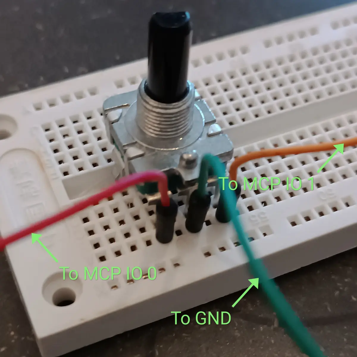
If you connect the encoder's center pin to the ground and the 2 pins to the MCP230xx's IO 0 and 1, the following code will do the polling:
pin0 = mcp.get_pin(0)
pin1 = mcp.get_pin(1)

# set pin 0 and 1 as input with a pull-up
pin0.direction = Direction.INPUT
pin0.pull = digitalio.Pull.UP
pin1.direction = Direction.INPUT
pin1.pull = digitalio.Pull.UP

last_position = 0
state = "00"
while True:
    time.sleep(0.01)
    newState = "{}{}".format("1" if pin0.value else "0", "1" if pin1.value else "0")
    if newState == state:
        continue

    if state == "11":
        if newState == "10":
            last_position += -1
        elif newState == "00":
            last_position += 1

    if state == "00":
        if newState == "11":
            last_position += -1
        elif newState == "10":
            last_position += 1

    print(state+""+newState+" "+str(last_position))
    state = newState
By happily turning the encoder, you can see the different states on the Raspberry terminal and the position of the encoder:
1100 8
0010 9
1011 9
1100 10
0010 11
1011 11
1100 12
0010 13
1011 13
1110 12
1000 12
0011 11
1110 10
1000 10
0011 9
1110 8
1000 8
0011 7
1110 6
1000 6
0011 5
1110 4
As you can see in the code, I don't process all possible states for several reasons: the precision obtained in this way is sufficient for what I'm going to do with it, and also because my encoder never passes through the '01' state (if you have an explanation, I'd love to hear it!).
I can see you saying that polling is ugly, and that it would be better to use the interrupt functions of the MCP and the Raspberry. I agree, but you should know that the above code consumes only 1% CPU on my old Raspberry PI 3B.
Soon I'll provide an example using interrupts, which will have the effect of reducing CPU consumption to nearly zero. The Adafruit library makes it easy to configure the MCP and enable interrupts. In the meantime, the detailed documentation of the MCP230xx library can be found here, with even a nice example of configuring an MCP230xx for a Raspberry PI 😊
Other interesting links:
- Adafruit using MCP230xx with Circuit Python
- Other Python library for MCP23017 without Circuit Python


Speak your mind: